The installation, mounting and getting the first ABS switch to work was pretty easy. However, was impossible to turn the ABS off on the go and was an absolute pain to turn it off after getting throw overs on the bike, during a trip.
As such, I decided to mount a handlebar one and resolve the above problems. I had only one problem: 15 amp switch. Someone from Facebook told be about relays and, after understanding what are those, I decided to go ahead with it.
Would have been pretty easy just to have it installed on the dash board with a 15A switch mounted and a fuse on the side. However, the 15A switches are pretty massive and I wouldn’t like the end result, so, I went to make one myself, small, pretty and with a relay attached.
I went to Bunnings to get some inspiration through their shelves. In the General Hardware Section I found 20 x 20 brackets. I purchased the 1mm one for $0.88. There are all kinds of brackets there, including angled ones if you want.
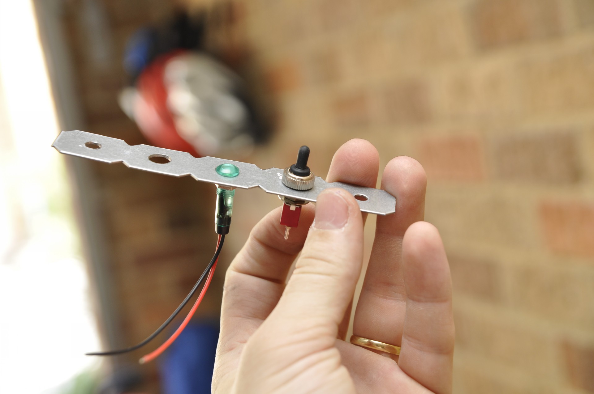
From Altronics I’ve purchased mini mini switches and covers for them.
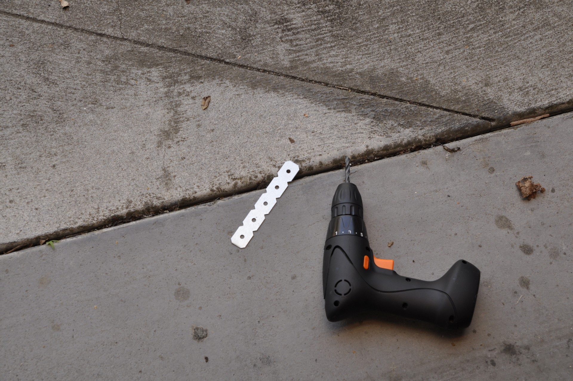
I decided I would need 3 of those holes for 2 switches and 1 light. So I went ahead and made the holes bigger with my electric screwdriver.
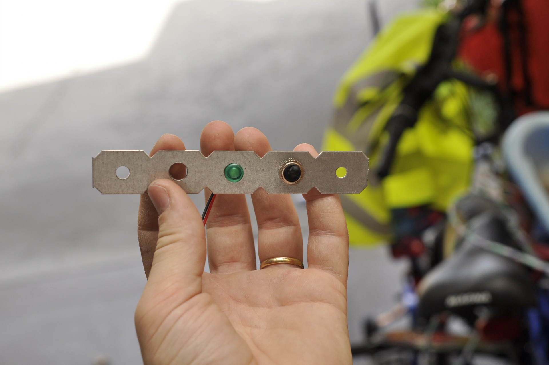
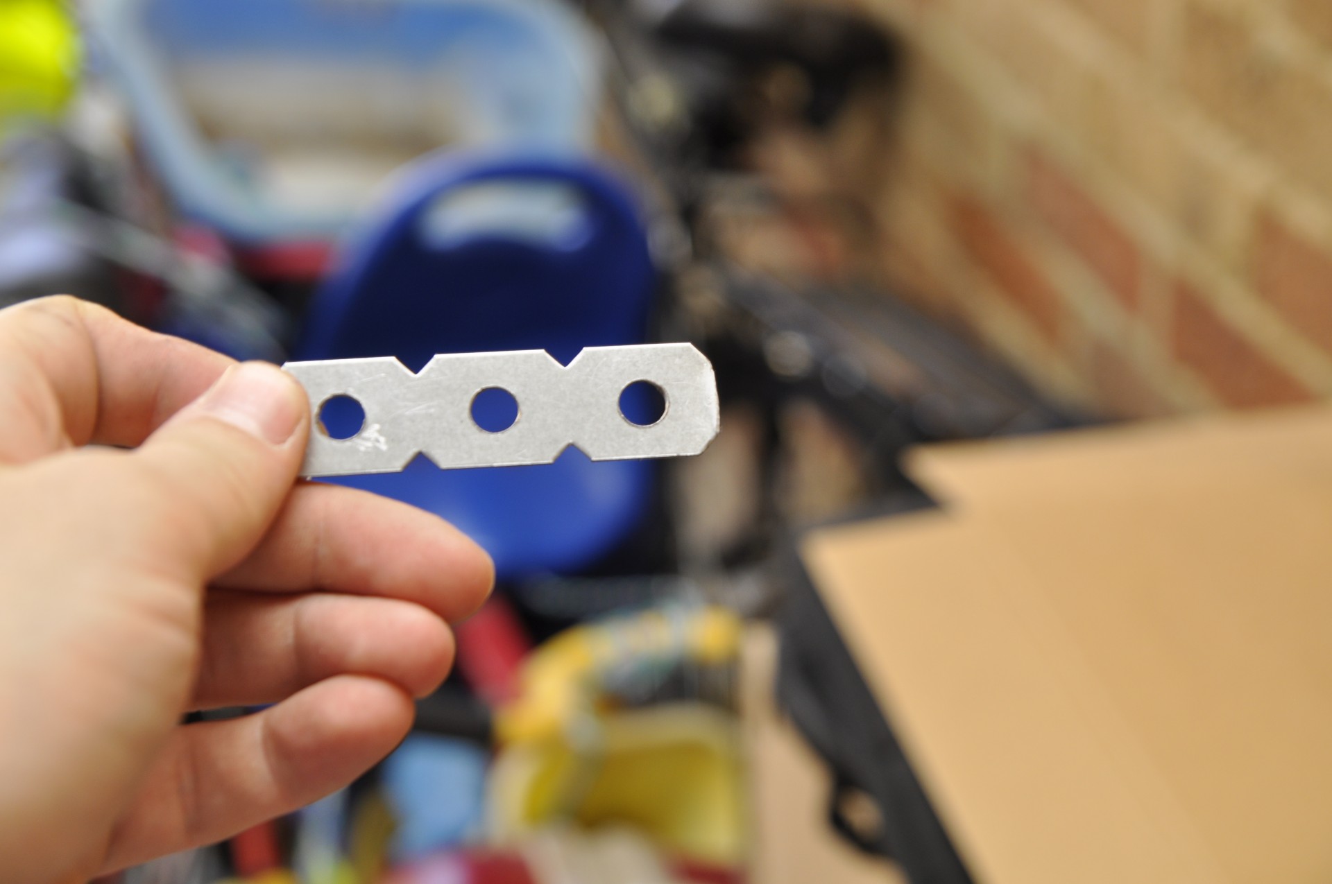
After that, I’ve spray painted the bracket in a black colour so it will match the bike, and voilà.
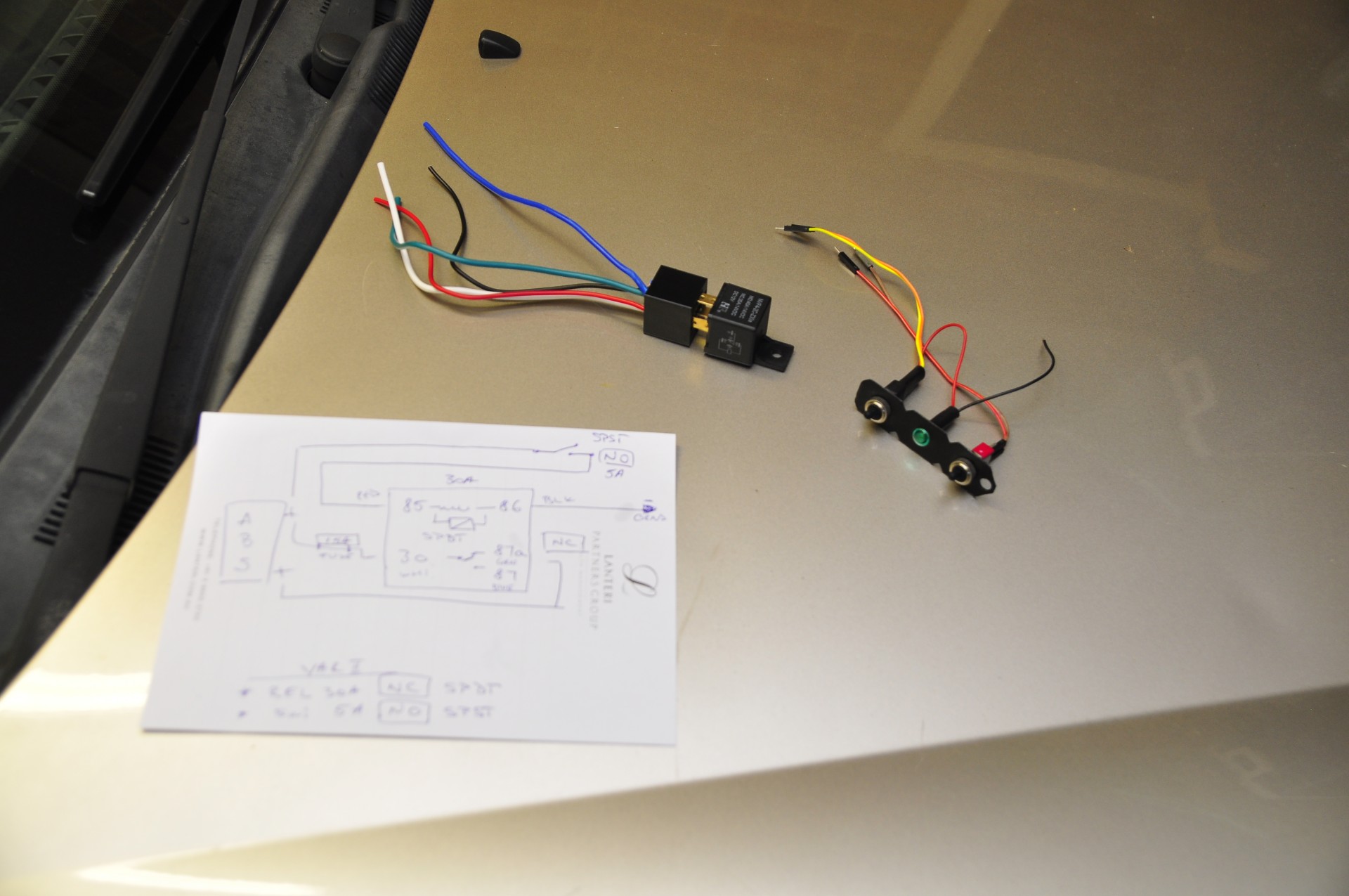
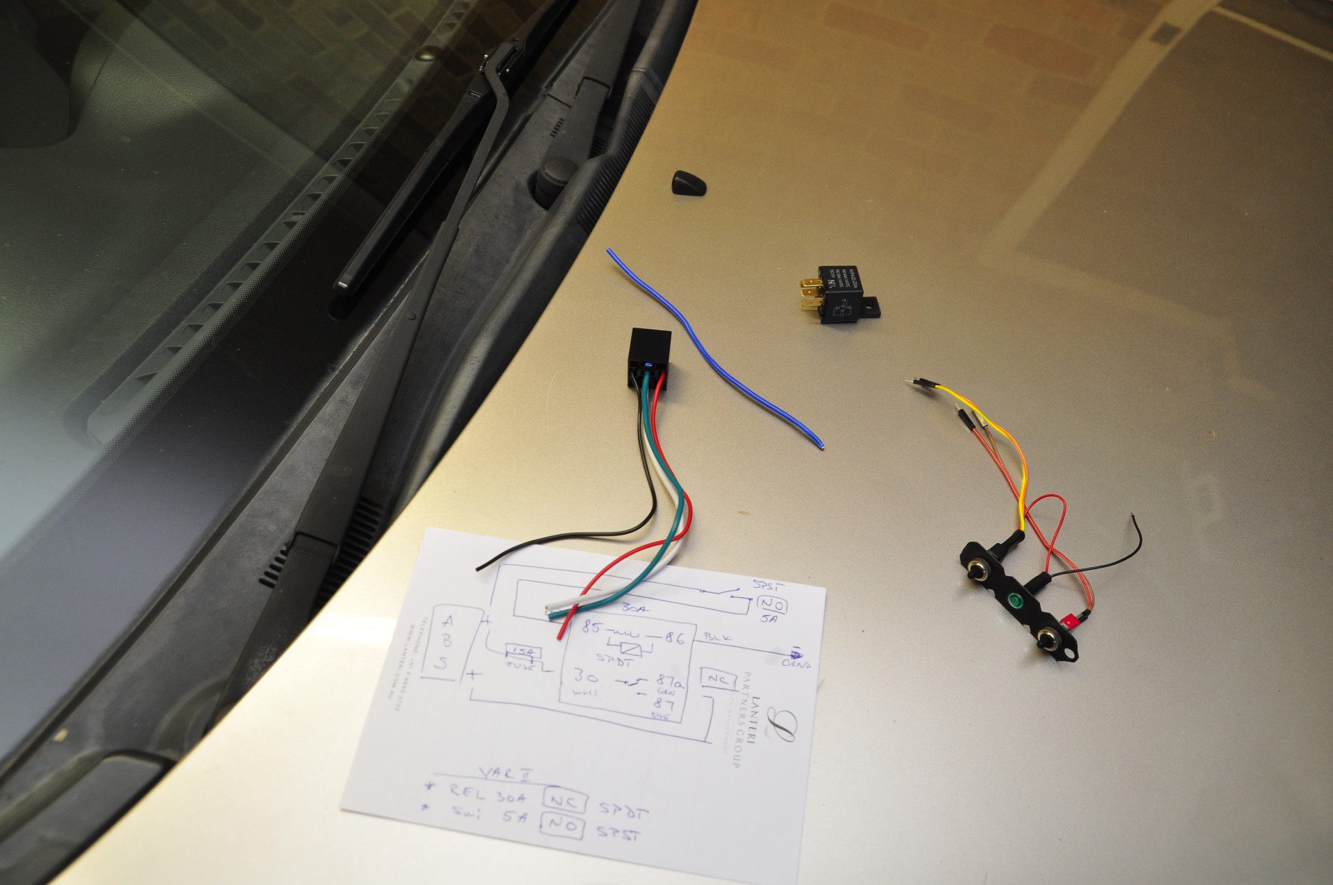
I had to learn a little bit about how relays work and after doing that and a bit of Facebook consultation, I decided to buy a 30A SPDT (Single Pole Double Throw) relay switch for my momentary ABS swich and a cradle.
This is the setup before anything.
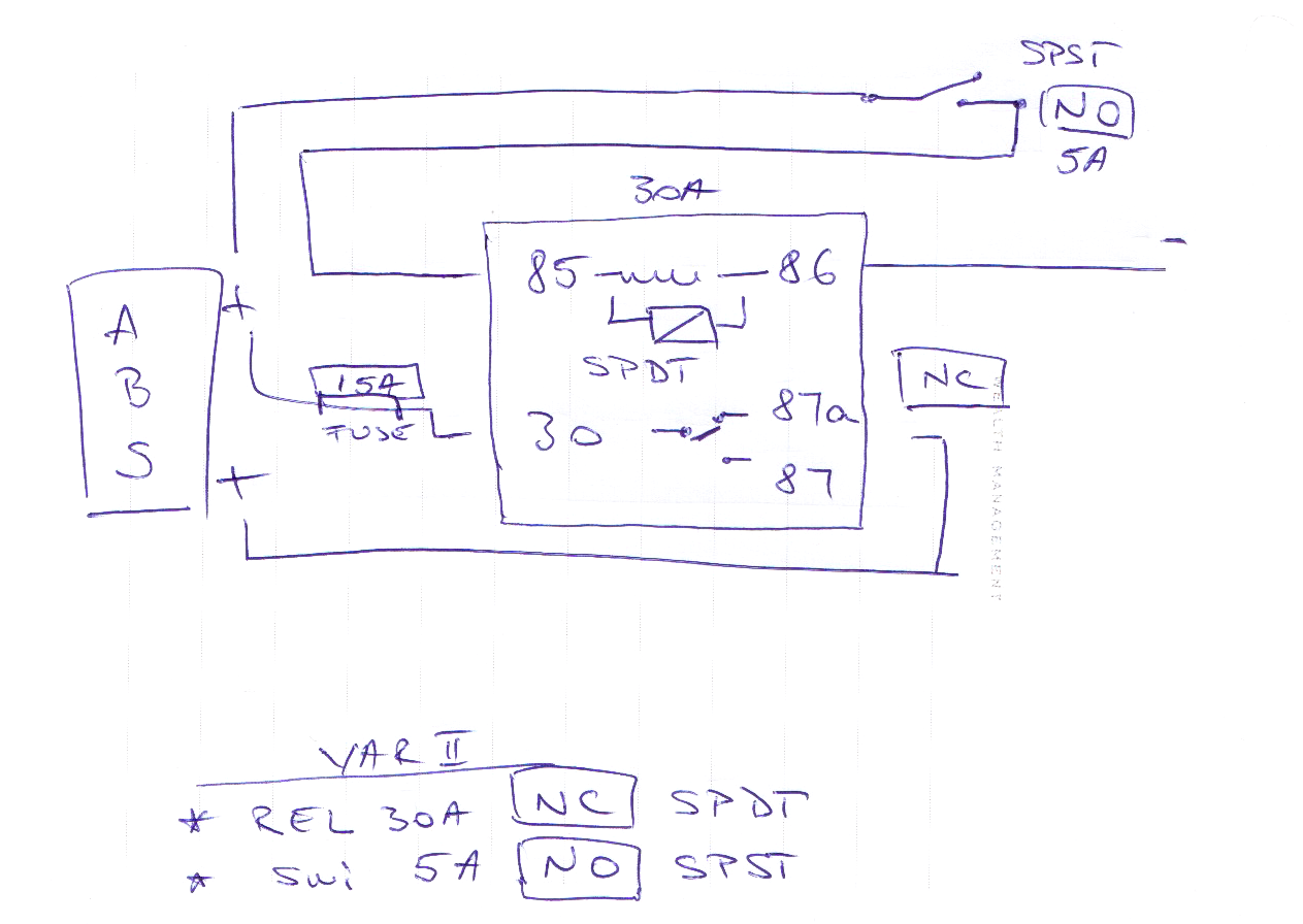
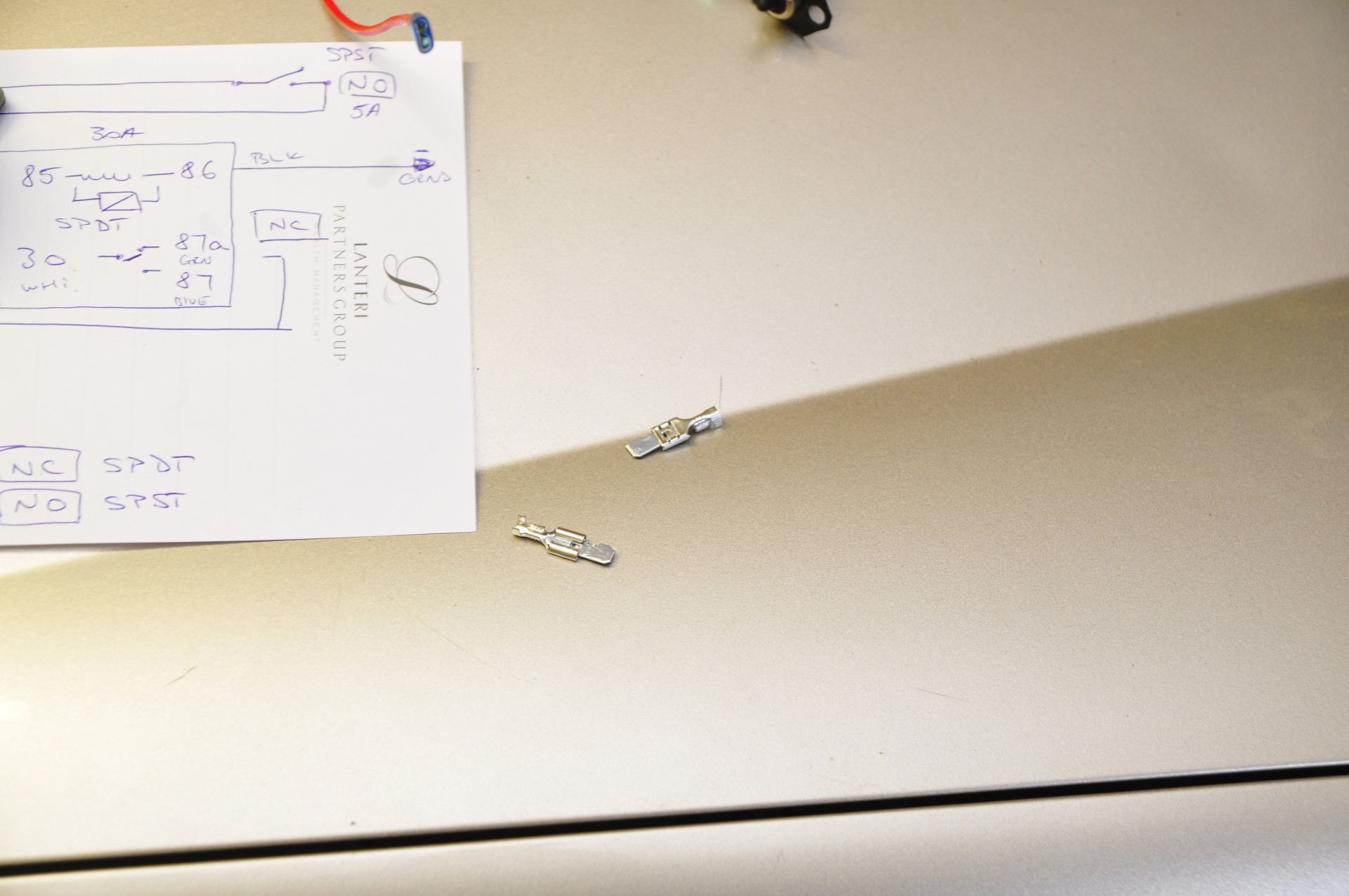
Here is my circuit that I drew after understanding how everything should work. It’s pretty simple once you understand the basics. My teaching videos: Video 1 and Video 2.
Because I didn’t use the 87 pole, I’ve cut it off. I’ve also cut a fuse in half and stripped the wiring so I can insert it into the fuse cradle. See the first ABS post to see how I’ve done that.

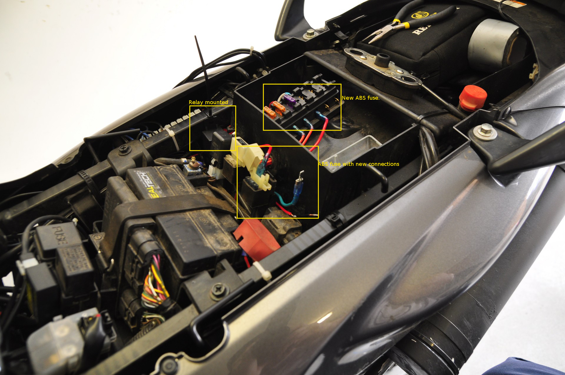
From this point, there were only 2 more cables, to the handlebar, for the switch.
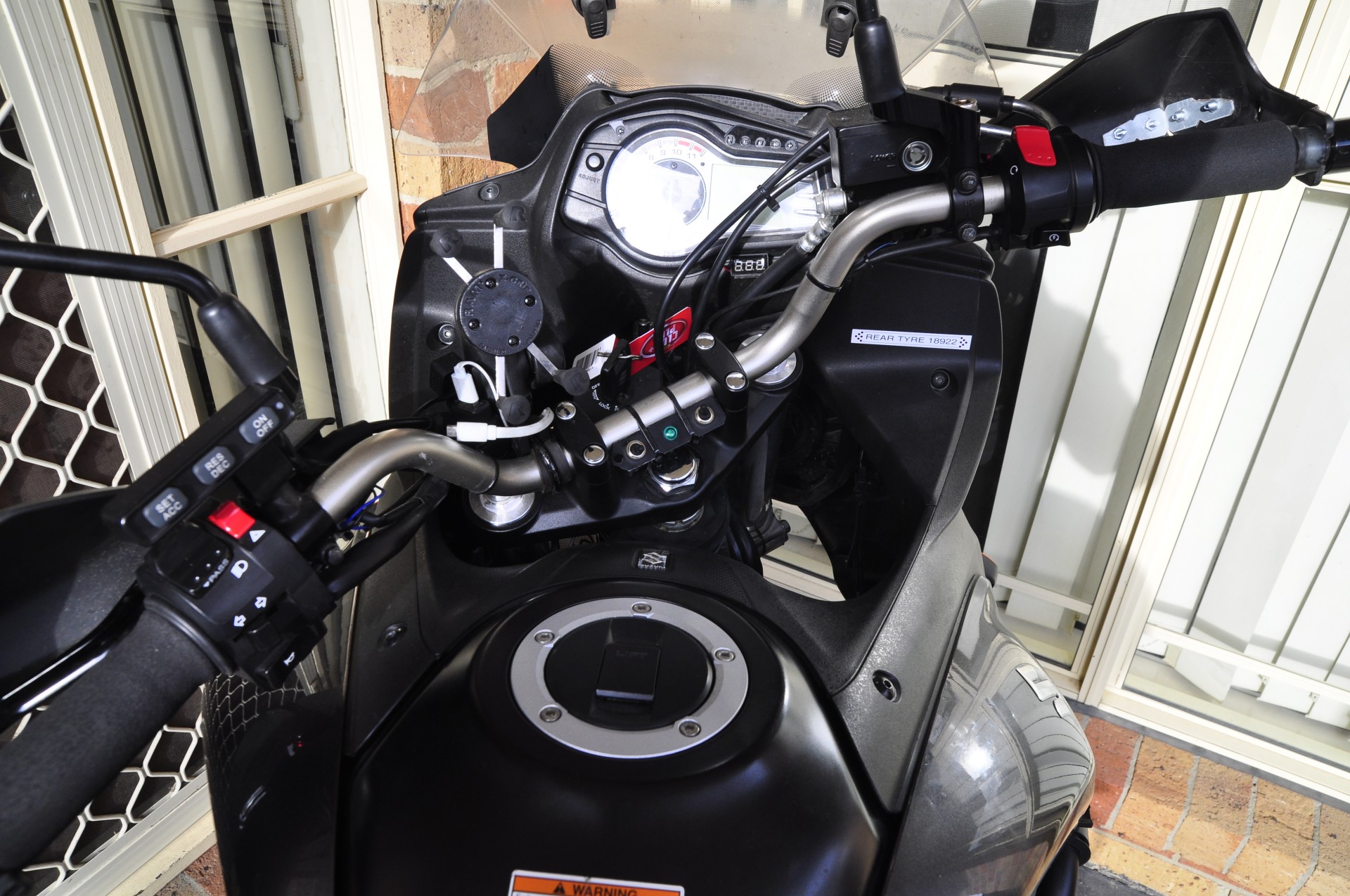
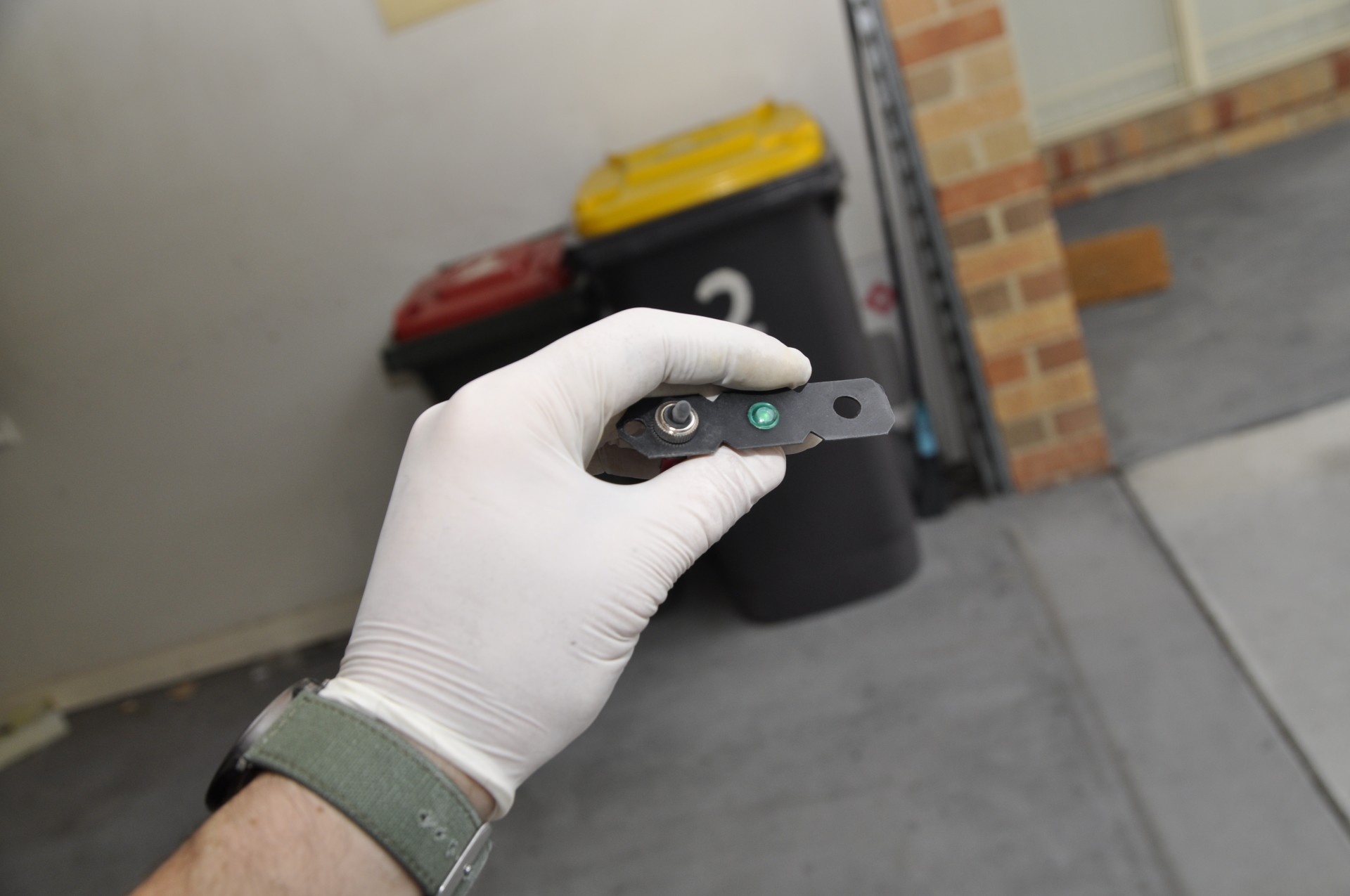
Here is the end result.

Mind you, the ABS switch its the one on the left, and always sitting in the down position as it is a momentary on/off which disables my ABS until I turn the bike back on.
The second switch its a normal switch which cuts off all my 7 USB charges from the bike. The green light bulb its connected to the USB charges as the ABS has one of its own, OEM.
The switches, on the back side were insulated with shrinking tube and silicone on top and on the edges and inside the tube itself.
Total cost for this: ~$12